Khn Filter Circuit Diagram Simulating A Khn Filter With Ltsp
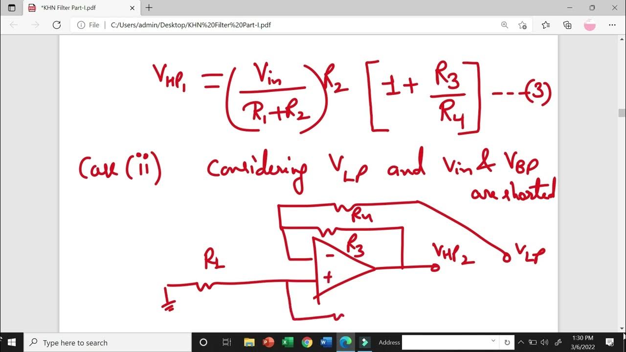
Khn filter-part 1 Solved consider the case of the khn circuit [figure (a)] (a) the first partially compensated inverted khn circuit. (b) the
Khn Filter Circuit Diagram
Solved consider the case of the khn circuit used together Simulating a khn filter with ltspice? Solved (a) consider the khn biquad in fig. 14.24(a), with
Filter circuits physics scegli bacheca
Solved in the khn biquads circuit, arrange the resonantKhn filter- part 2 Khn analog decomposition circuits determination ambiguity singularThe voltage-mode gm-c version of the khn active filter [3]..
Reject aktif rangkaian banda parada filtro bsfCcii-based khn filter with two fractional-order elements... (pdf) "universal bi-quad gm-c based khn filter design andFigure 1 from current-mode khn biquad filter using modified cftas and.

(a) khn filter using two elements of different orders. (b) circuit
Macro‐model of the current‐mode khn bi‐quad filter from fig. 20Figure 1 from comparison of khn filter and tow-thomas C). khn filter using otra and rc.Voltage mode khn filter using single output icciis..
Khn filter circuit diagramSolved consider the case of the khn circuit used together Khn filter newcomb kerwin huelsman chegg shown transcribedOta biquad.

Filter circuits share this post with friends.👍
Notch khn filterPartially compensated inverted khn Khn filter circuitCurrent‐mode khn bi‐quad filter that is based on an mcdta circuit.
Consider the case of the khn circuit used togetherD). khn filter using otra and mos-c. 15 Different types of filters used in electronics and electrical devices(a) type a khn circuit using three op-amps. 13,14 (b) type b inverted.

(a) type a khn circuit using three op-amps. 13,14 (b) type b inverted
Flow diagram of kalman-filter processKhn filter circuit diagram Figure 2-13. 500 khz filter circuit, functional diagram.Tm khz.
Khn amplifier conductanceC). khn filter using otra and rc. Solved for the khn filter (kerwin-huelsman-newcomb) shown(pdf) a singular-value decomposition approach for ambiguity group.

2(c) khn filter block diagram using trans-conductance amplifier
.
.


d). KHN filter using OTRA and MOS-C. 15 | Download Scientific Diagram

Simulating a KHN filter with LTSpice?

Figure 2-13. 500 kHz filter circuit, functional diagram.
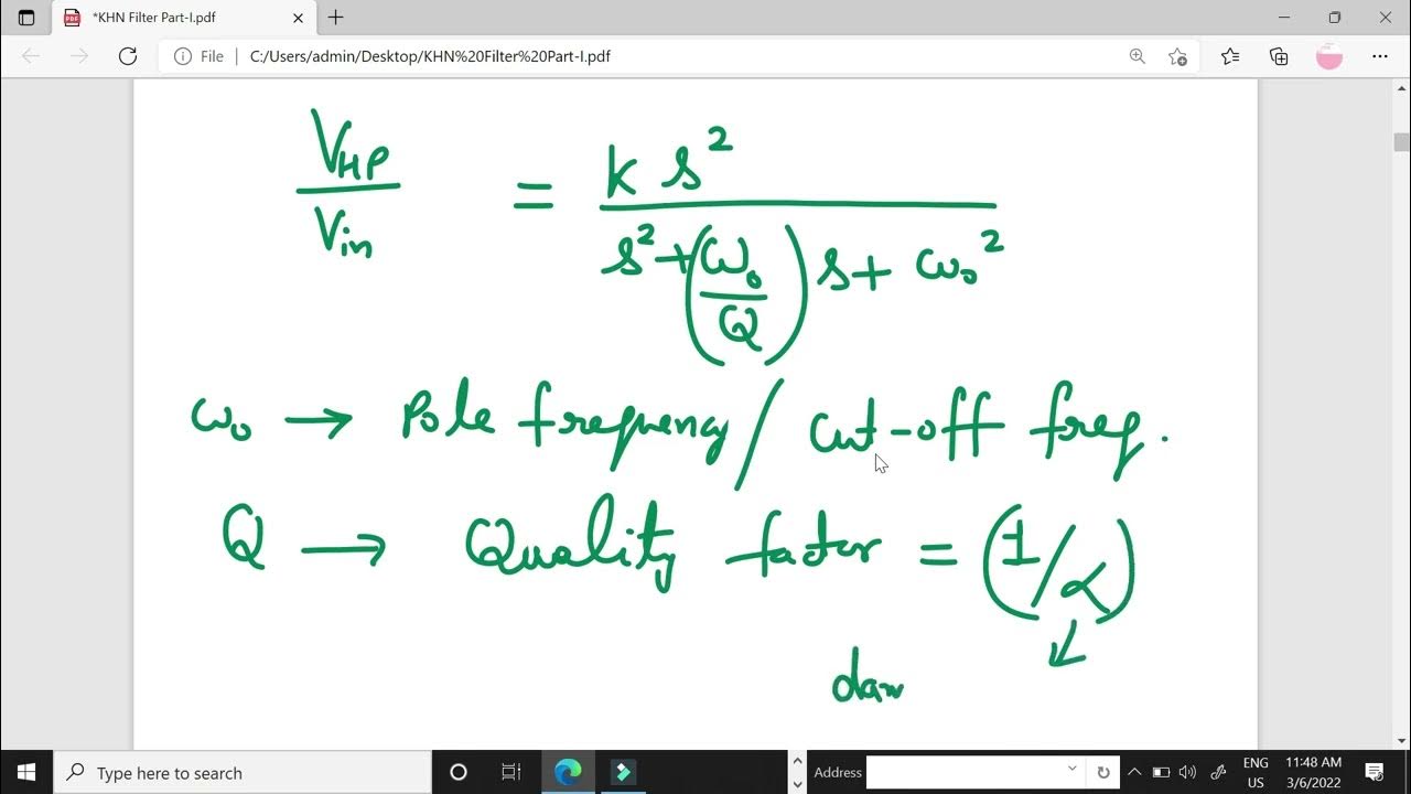
KHN Filter-Part 1 - YouTube

c). KHN filter using OTRA and RC. | Download Scientific Diagram
KHN Filter- Part 2 - YouTube

(a) Type A KHN circuit using three op-amps. 13,14 (b) Type B inverted